Is your Hisense air conditioner suddenly blowing warm air, shutting down entirely, or flashing a cryptic code like 36, 33, or E1 on the digital display? A malfunctioning AC always feels like an emergency, but those flashing letters and numbers are your system’s built-in self-diagnosis tool pinpointing the exact mechanical or electrical failure.
Because Hisense manufactures both classic standard-efficiency splits and highly advanced Inverter systems, their diagnostic matrix uses two distinct code families. Classic units typically display E-Series codes for sensor and communication faults, while newer inverter units display specific numeric codes like 36 (Indoor/Outdoor Communication Error) or 41 (IPM Protection).
Instead of hunting down the correct user manual for your specific generation of Hisense AC, use our Official Hisense AC Error Code Decoder below. We have compiled the complete master matrix for both classic and inverter models. Simply select your flashing code to instantly reveal the hidden cause and the step-by-step DIY or professional solution.
The definitive diagnostic tool for Hisense Inverter and Classic Split Systems.
⚠️ Pro Safety Tip: While cleaning your filters to clear a poor airflow issue or resetting the breaker to clear a temporary glitch are safe DIY fixes, errors involving Inverter IPM Protections (41), Compressor Phase Losses (39), or High Voltage Overcurrents (34) should always be handled by our licensed HVAC technicians to prevent severe electrical hazards.
How to check hisense aircon error codes?
When the hisense ac failure occurs, the aircon will show the error codes in 3 ways.
- outdoor control board
- wire remote controller
- display panel
The Error inquiry should be operate in the stand-by state, keep 5 sec press and hold on the Emergency button, the error code will be displayed in 10 sec, then the indoor unit display will recovery to the original. If two or more malfunction happened, each error code will be displayed alternatively. If the appliance could save information under no power condition, then the error code can be inquired as aforesaid with stand-by
state after power resume.
NOTE:
- If wire remote controller display of “FE”, that is the wire controller can’t receive the
signals of indoor unit control board - If wire remote controller display of “LOW” ,that is the ambient temperature below ten
degrees or the indoor unit control board don’t receive wire controller signals
Hisense AC error codes list
| Error code | Possible causes |
|---|---|
| E2 | 1. It is normally for protection, When the indoor pipe temperature between 53℃ <T<63℃, the outdoor fan motor will stop running. When the indoor coil temperature is higher than 63℃, the error code will display. After the indoor pipe temperature is lower than 49℃, the air conditioner will restart normally. 2. The indoor coil temperature sensor is loose. 3. The indoor coil temperature sensor is failure. 3. The indoor control board is failure. |
| E4 | 1. There are something block the indoor fan motor. 2. The fan motor cord connect loose. 3. The fan motor is failure. 4. The indoor control board is failure. |
| EA | 1. The connection between the display board and control board is loose. 2. The indoor control board is failure. 3.The wiring of the display board is failure. |
| 1 | 1. The outdoor temperature sensor loose. 2. The outdoor temperature sensor is failure. 3. The indoor control board is failure. |
| 2 | The outdoor coil temperature sensor short circuit or open circuit. |
| 3 | Current protective device. |
| 4 | EEprom Data error or EE chip fault. |
| 5 | Refrigeration indoor coil temperature is too low or heating the indoor coil temperature too high. |
| 6 | AC motor fault. |
| 7 | Outdoor continuously for 2 minutes without receipt of indoor communication data |
| 8 | Phase current imbalance. |
| 9 | Current U phase. |
| 10 | Current V phase. |
| 11 | Three phase power supply wiring line sequence error. |
| 12 | Phase detection phase. |
| 13 | Compressor overheating protector tripping. |
| 14 | Too high system pressure leads to high pressure switch tripping or pressure sensors to detect the pressure too high to achieve shutdown protection pressure. |
| 15 | System low pressure causing low pressure switch tripping or pressure sensors to detect the pressure is too low to achieve the shutdown protection pressure. |
| 16 | The outdoor coil temperature is too high to reach refrigeration temperature shutdown protection. |
| 17 | Exhaust temperature sensor short circuit or open circuit. |
| 18 | Power input AC voltage is too low or too high. |
| 19 | Exhaust temperature sensor short circuit or open circuit. |
| 20 | 1. The motor cord connection loose. 2. The motor is invalid. 3. The outdoor fan is blocked. 4. The outdoor control board is invalid. |
| 21 | The outlet of the condenser temperature sensor short circuit or open circuit. |
| 22 | The outlet of the condenser temperature sensor short circuit or open circuit. |
| 23 | Expansion valve A tube sensor short circuit or open circuit. |
| 24 | Expansion valve B tube sensor short circuit or open circuit. |
| 25 | Expansion valve C tube sensor short circuit or open circuit. |
| 26 | Expansion valve D tube sensor short circuit or open circuit. |
| 27 | 1. The pressure switch is working. 2. The pressure switch is invalid. 3. The outdoor control board is invalid. |
| 28 | Expansion valve B thick pipe sensor short circuit or open circuit. |
| 29 | Expansion valve C thick pipe sensor short circuit or open circuit. |
| 30 | Expansion valve D thick pipe sensor short circuit or open circuit. |
| 33 | 1. The indoor room temperature sensor loose. 2. The indoor room temperature sensor is failure. 3. The indoor control board is failure. |
| 34 | 1. The indoor coil temperature sensor loose. 2. The indoor coil temperature sensor is failure. 3. The indoor control board is failure. |
| 36 | 1. The interconnection cord loose. 2. The interconnection cord is not in proper order. 3. The indoor control board is invalid. 4. The outdoor control board is invalid. |
| 38 | 1. The EEPROM chip loose. 2. The indoor control board is failure. |
| 39 | 1. There are something block the indoor fan motor. 2. The fan motor cord connect loose. 3. The fan motor is failure. 4. The indoor control board is failure. |
| 41 | The indoor control board is failure. |
| 42 | 1. It is normally for protection, When the indoor pipe temperature below T<-1℃(-7℃).Outdoor fan motor and compressor will stop running. When the Indoor pipe temperature is higher than -1(-7℃),the unit will restart normally. 2. The indoor coil temperature sensor is loose. 3. The indoor coil temperature sensor is failure; d. The indoor control board is failure. |
| 43 | 1. It is normally for protection, When the indoor pipe temperature between 53℃ < T<63℃, the outdoor fan motor will stop running. When the indoor coil temperature is higher than 63℃, the error code will display. After the indoor pipe temperature is lower than 49℃, the air conditioner will restart normally. b. The indoor coil temperature sensor is loose. c. The indoor coil temperature sensor is failure. d. The indoor control board is failure. |
| 44 | L Pressure sensor fault. |
| 45 | IPM fault. |
| 46 | IPM Communication fault. |
| 47 | The exhaust temperature is too high to reach shutdown temperature. |
| 48 | Outdoor DC fan fault. |
| 49 | Outdoor DC fan fault. |
| 90 | Forced expansion valve. |
| 91 | IPM temperature is too high to reach shutdown temperature. |
| 92 | Compression ratio is too large to stop. |
| 97 | Four way valve commutation failure. |
Checking the components of hisense aircon
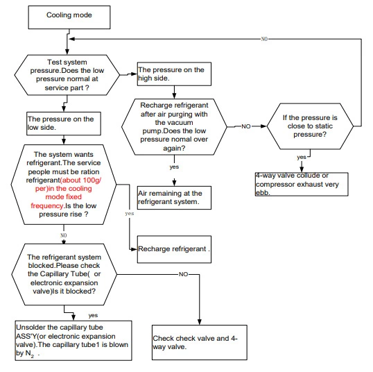
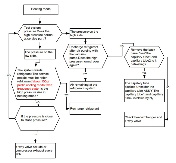
Examine the system flow
Test hisense cooling mode aircon system flow.
Test hisense heating mode aircon system flow.
Examine indoor fan motor
Test in resistance
TOOL: Multimeter.
Test the resistance of the main winding. The indoor fan motor is fault if the resistance of main winding 0 (short circuit) or ∞(open circuit).
Test in voltage
TOOL: Multimeter.
Insert screwdriver into to rotate indoor fan motor slowly for 1 revolution or over, and measure voltage “YELLOW” and “GND” on motor. The voltage repeat 0V DC and 5V DC.
Notes:
- Please don’t hold motor by lead wires.
- Please don’t plug IN/OUT the motor connecter while power ON.
- Please don’t drop hurl or dump motor against hard material. Malfunction may not be observed at early stage after such shock. But it may be found later, this type of mishandling void the warranty.
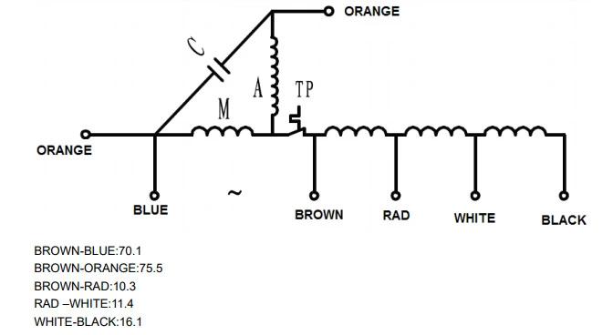
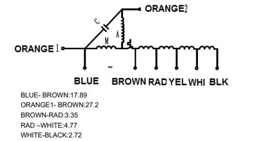
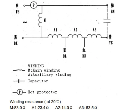
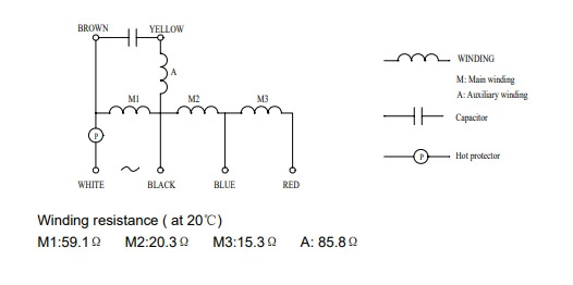
AUD-18HX4SNL indoor fan motor circuit diagram
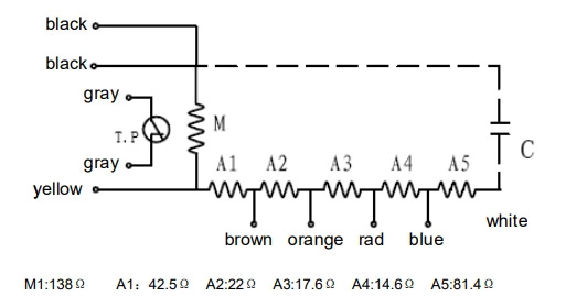
AUC-18HR4SA indoor fan motor circuit diagram
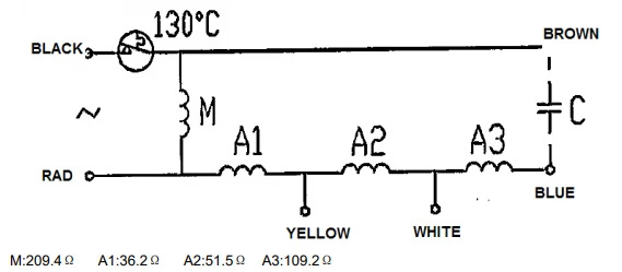
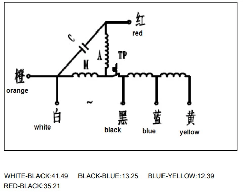
AUD-24HX4SLH indoor fan motor circuit diagram
AUC-24HR4SGA indoor fan motor circuit diagram
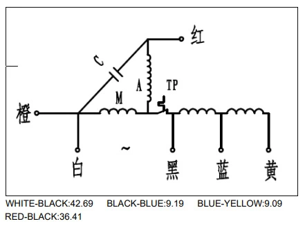
AUD-36HX4SHH indoor fan motor circuit diagram
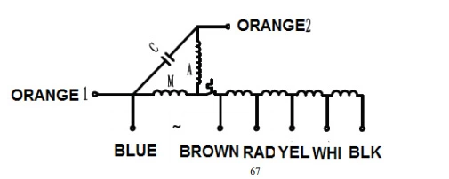
AUC-36HR4SGA indoor fan motor circuit diagram
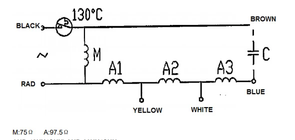
AUD-48HX4SHH indoor fan motor circuit diagram
AUC-48HR4SHA indoor fan motor circuit diagram
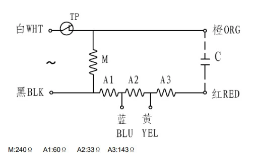
AUV-36HR4SAB indoor fan motor circuit diagram
AUV-48HR6SPC indoor fan motor circuit diagram
Examine outdoor fan motor
Test in resistance.
TOOL: Multimeter.
Test the resistance of the main winding. The outdoor fan motor is fault if the resistance of main winding 0 (short circuit) or ∞(open circuit).
Notes:
- Please don’t hold motor by lead wires.
- Please don’t plug IN/OUT the motor connecter while power ON.
- Please don’t drop hurl or dump motor against hard material. Malfunction may not be observed at early stage after such shock. But it may be found later, this type of mishandling void the warranty.
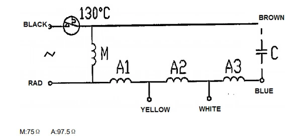
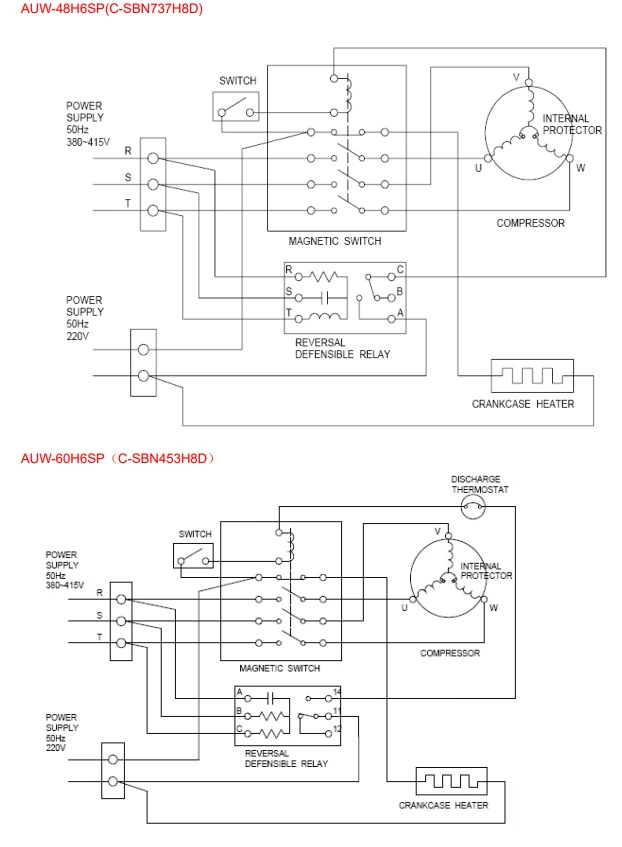
AUW-48H6SP and AUW-60H6SP outdoor fan motor circuit diagram
AUW-36H6SA outdoor fan motor circuit diagram
Examine compressor
Test in resistance.
TOOL: Multimeter.
Test the resistance of the winding. The compressor is fault if the resistance of winding 0 (short circuit) or ∞(open circuit
Familiar error:
- Compressor motor lock.
- Discharge pressure value approaches static pressure value. Please refer to our latest guide to learn how to measure static pressure.
- Compressor motor winding abnormality.
Notes
- Don’t put a compressor on its side or turn over.
- Please assembly the compressor in your air conditioner rapidly after removing the plugs. Don’t place the comp. In air for along time.
- Avoiding compressor running in reverse caused by connecting electrical wire incorrectly.
- Warning! In case AC voltage is impressed to compressor, the compressor performance will below because of its rotor magnetic force decreasing.
Examine inductance
Familiar error:
- Sound abnormality
- Insulation resistance disqualification.
Examine fuse
Checking continuity of fuse on PCB ASS’Y.
- Remove the PCB ASS’Y from the electrical component box. Then pull out the fuse from the PCB ASS’Y
- Check for continuity by a multimeter
Examine capacitor
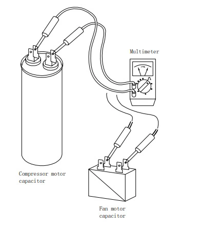
- Remove the lead wires from the capacitor terminals, and then place a probe on the capacitor terminals.
- Observe the deflection of the pointer, setting the resistance measuring range of the multimeter to the maximum value.