In large-scale chilled water or heating systems, a Balancing Valve is the component that ensures hydraulic equilibrium. Without them, water follows the “path of least resistance,” flooding the units closest to the pump with excess flow while leaving distant rooms under-conditioned. A balancing valve acts as a calibrated bottleneck, adding a precise amount of resistance to ensure that every terminal unit receives its design flow rate.
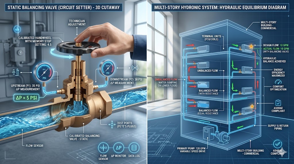
Modern hydronic systems rely on two main types: Static Balancing Valves (manual) and Dynamic Balancing Valves (automatic). A static valve (like a circuit setter) requires a technician to manually measure the pressure drop across the valve and adjust it to a specific point on a flow chart. A dynamic valve, however, automatically adjusts its internal opening to maintain a constant flow regardless of pressure fluctuations elsewhere in the building. Proper balancing is the only way to prevent energy waste and ensure consistent comfort across a multi-story building.
To see if your building’s hydronic flow is optimized or if you’re suffering from “overflow” energy waste, use the Hydronic Flow & Performance Auditor below.
What is a balancing valve in HVAC
A balancing valve is an automatic valve used in an HVAC system that depends mainly on the flow of water through its system to provide cooling and hearing effects at homes or in offices as the situation may require. In designing balancing valves, updated flow technology is employed to ensure that the required flow rate is achieved every time, regardless of the number of times the pressure level within the system changes.
Uses of balancing valves in HVAC

There are different types of balancing valves ( refer to later sections of this article for more details about this), however, all of these varieties are used for three major purposes.
- To ensure that fluids are evenly distributed among the various flow branches.
- To control the intensity of the water temperature of the heating and cooling system to keep them at a moderate level.
- And lastly, they are used as counterbalancing forces for dualized action cylinders.
💡 Pro Diagnostic Tip: Proper balancing is the only way to maximize your system’s Enthalpy efficiency. If water flows too fast through a coil, it doesn’t have enough time to exchange heat, meaning you’re spending pump energy without actually cooling the room.
Balancing valve working principle
In light of the various usage of balancing valves in HVAC discussed above, it is obvious that the role it plays in an HVAC system can not be overemphasized. However, before a balancing valve can be put to use, certain conditions must be met.
- The body material of the valve must be made of either cast iron or cast steel.
- The level of pressure, while it is in use, must be between 0.6 – 0.4 MPA
- The working temperature level must be maintained between -5°c and -350°c
- The caliber of the valve must be between DN15-DN300
- The connection mode of your balancing valve can be any of Internal, Flange, or Thread.
- The driving mode must be either electric or manual.
- The manufacturing standard must be in line with the national standard.
What is water balancing in an HVAC system
Water balancing is used in HVAC to describe a situation whereby the flow of water through components like the coils is regulated to ensure that neutrally balanced and comfortable air is distributed throughout the building. This must be done at intervals to avoid discomfort, inefficient HVAC system, and breathing in of low-quality air. Water balancing is done by water balance technicians and they do this by professionally balancing the water so that the number of fluids coming into the system equals the amount of water leaving that system.
How does the balancing valve work
A typical balancing valve is equipped with a sealed thermostatic motor that is usually located in the flow stream of the valve. It responds to temperature by opening and closing the valves to control the flow of water through the HVAC system.
When the temperature is heated up, the thermostat will expand, which will cause the valve to close. And when the temperature drops, the thermostat will contract to open up the valve seat. On a similar note, the motion of the valve stem is controlled by calibrating the opposing spring of the thermostat with the direct motion of the motor.
Note: The valve seat is not designed to be completely sealed, there will always be a small opening where water can flow through the thermostat for it to respond appropriately to the prevailing level of temperature.
Balancing valve types in HVAC
There are three major types of balance valves in HVAC. Provided below are their names with specifications.
Calibrated balancing valves
This is one of the oldest types of balancing valves we have in HVAC because its usage dates back to the 90s. Calibrated balancing valve is also called circuit setters. Calibrated balancing valve usually has a valve and a pressure point located on the sides of the valve. Although they are usually calibrated from the factory, you can always refer back to the performance curve or chart that comes with it for a proper understanding of the configuration. Calibrated balance valve is of different types namely; Globe type, plug type, butterfly type, eccentric type.
Flow measuring venturi balance valve
The Flow measuring venturi balance valve with a butterfly valve combines two separate components for optimal operation. The valve is positioned at a minimum of 10 pipe diameters away from the device used in measuring the rate of flow. When the valve is closed, the flow rate will be restricted and the rate at which the flow drops will be derived from the venturi plate.
Automatic flow limiting valve
An automatic flow limiting valve is easily identified because its valve stem will come with a controller. The controller is designed to adjust the valve accordingly (whether to open or close) and it is usually connected to the thermostat (or any activating device). If the thermostat needs to be cooled down due to overheating, the controller will close the stem, and if the thermostat requires some heat, the controller will open the stem.
Balancing valve vs check valve
Check valves are used majorly for pipelines to avoid backflow. But in general, they are used as a one-way valve because they allow water to flow freely in one way, however, if the flow is interrupted, the valve will close automatically to protect the valve, pipe, and the pump.
The key differences between a check valve and a balance valve include:
- Compared to the balance valve, the check valve is very cheap.
- Check calves are non-modulating valves, while balance valves are modulating valves.
- Balance valve is best used for motion control and load holding, while the check valve cannot control loads while in motion and is used for simple load holding.
Balancing valve vs circuit setter
The circuit setter valve has an inbuilt balance valve that allows it to control the flow of water so that the HVAC system can be automatically balanced without being manually operated. The circuit setter also comes with the monitoring and measuring points which makes it possible for the flow of water to be directed to one particular section of the system while completely shutting the flow of water to another part of the system.
Differences between balance valve and circuit setters.
- Circuit setter is automatic, while balance valve is manually operated.
- Balance valve is best used in small residential buildings, while circuit setter is best used for commercial buildings.
- Circuit setter can efficiently control the distribution of water to a particular part thereby saving energy, while in balance valve, flow is not efficiently controlled and consumes more energy.
- Circuit setter is expensive, while balance valve is cheaper.
Balancing valve vs control valve
Just like every other type, control valves are used to regulate the flow of fluid, pressure, temperature, and water level by constricting or expanding the entry point of the flow.
Differences between balance valve and control valve
- The unit cost of a balance valve is lower compared to that of the control valve.
- Balance valve is more labor-intensive because the flow is mostly regulated manually, while the control valve is less labor-intensive because the only thing manually done is flow verification.
- Irrespective of the pressure level, the control valve maintains the standard flow, while a change in pressure will cause a decrease or increase in flow rate.
- A control valve requires fewer valves compared to a balance valve.
💡 Pro Diagnostic Tip: While a balancing valve sets the ‘speed limit’ for water, a Control Valve is what actually modulates the flow based on your thermostat’s demand. Think of balancing as the ‘alignment’ and control as the ‘steering.’
How to install balancing valves in HVAC
Follow the guidelines below to help you through the stages involved in the installation of balancing valves.
- The valve should be positioned on the return side of the terminal unit.
- The gate or ball valve should be used to shut off the distribution side of the terminal unit.
The location of the valve will ensure that the coil has positive pressure to allow enough air to be removed through the air vent. And it will also permit the balancing and supply valves to be shut so that the terminal coil or control valve is serviced.
Note: Your installation must be in line with the proper flow direction. This is usually indicated by an arrow located on the valve. Also, you should ensure that the valve is installed in an upright position and the pressure port must be fully accessible so that it can be easily hooked up with the measuring hoses.
How to adjust balancing valves
Follow the steps below to help you navigate your way through the processes involved in adjusting a balancing valve.
- Connect the valve’s two metering ports and the circuit balancing equipment.
- Using the balancing valve, determining the expected flow rate.
- The handwheel must also be adjusted to ensure an efficient flow rate.